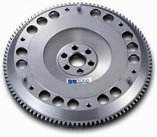
Showing posts with label flywheel. Show all posts

Monday 18 November 2013

Stability of Governors

A governor is said to be stable when for every speed within the working range there is a definite configuration i.e. there is only one radius of rotation of the governor balls at which the governor is in equilibrium.
For a stable governor, if the equilibrium speed increases, the radius of governor balls must also increase. 


Inertia Governors

This works on a different principle. The governor balls are arranged so that the inertia forces caused by angular acceleration or retardation of the governor shaft tend to alter their positions. The amount of the displacement of the balls is controlled by springs and
the governor mechanism to alter the supply of energ y to the engine. 
 
The advantage of this type of governor is that the positions of the balls are affected by
the rate of change of speed of the governor shaft.Consequently, a more rapid response
to a change of load is obtained, since the action of the governor is due to acceleration
and not to a finite change of speed. The advantageis offset, however, by the practical
difficulty of arranging for a complete balance of the revolving parts of the governor. For
this reason centrifugal governors are much more frequently used. 


Inertia Governors


Centrifugal Governors

The centrifugal governors are based on the balancing of centrifugal force on the rotating balls by an equal and opposite radial force, known as the controlling force* .It consists of two balls of equal mass, which are attached to the arms as shown in Fig . These balls are known as governor balls or fly balls.The balls revolve with a spindle, which is driven by the engine through bevel gears. The upper ends of the arms are pivoted to the spindle, so that the balls may rise up or fall down as they revolve about the vertical axis. The sleeve revolves with the spindle; but can slide up and down. The balls and the sleeve rises when the spindle speed increases, and falls when the speed decreases. In order to limit the travel of the sleeve in upward and downward directions, two stops S,S are provided on the spindle.

The sleeve is connected by a bell crank lever to a throttle valve. The supply of the working fluid decreases when the sleeve rises and increaseswhen it falls. When the load on the engine increases, the engine and the governor speed decreases. This results in the decrease of centrifugal force on the balls. Hence the balls move inwards and the sleeve moves downwards. The downward movement of the sleeve operates a throttle valve at the other end of the bell crank lever to increase the supply of working fluid and thus the engine speed is increased.

Hence, the extra power output is provided to balance the increased load. When the load on the engine decreases, the engine and the governor speed increases, which results in the increase of centrifugal force on the balls. Thus the balls move outwards and the sleeve rises upwards. This upward movement of the sleeve reduces the supply of the working fluid and hence the speed is decreased. Hence, the power output is reduced.


http://enginegearclutch.blogspot.in/


Other Topics

Types of Governors

Governors

Flywheel which minimizes fluctuations of speed with
in the cycle but it cannot minimize fluctuations due to load variation. This means flyw
heel does not exercise any control over mean speed of the engine. To minimize fluctuat
ions in the mean speed which may occur due to load variation, governor is used. The
governor has no influence over cyclic speed fluctuations but it controls the mean speed o
ver a long period during which load on the engine may vary. 
 
The function of governor is to increase the supply of working fluid going to the prime- mover when the load on the prime-mover increases and to decrease the supply when the load decreases so as to keep the speed of the prime-mover almost constant at different loads.
 
Example: when the load on an engine increases, its speed decreases, therefore it becomes necessary to increase the supply of working fluid. On the other hand, when the load on the engine decreases, its speed increases and hence less working fluid is required.
When there is change in load, variation in speed also takes place then governor operates a regulatory control and adjusts the fuel supply to maintain the mean speed nearly constant. Therefore, the governor automatically regulates through linkages, the energy supply to the engine as demanded by variation of load so that the engine speed is maintained nearly constant. 


Wednesday 13 November 2013

Flywheel: FACTOR

Maintenance:
Service- and maintenance works of the rotating converter can be done by every trained technician. A static converter can only be maintained from a specialist from the supplier/OEM. This can influence the service cost significantly.

MTBF-value:
The MTBF-Value (meantime between failure) of rotary converter is above 50.000 hrs. The MTBF of static converters is significanly lower due to the higher number of parts and electronic components.

Spares:
Spares for rotary converter are available in almost every country of the world.

Grid loading effect:
When planning static systems, you have to consider, that because of current and voltage interferences caused by static converters the Mains transformer has to be oversized by about 20%. Further on only such consumer can be connected to the transformer which are not influenced by the interferences. (Problems with UPS or diesel gen sets).

Efficiency:
The efficiencies of rotary converter and static converters are almost the same. The additional losses caused by the inverters’s harmonics are not included.

Distortion factor:
The intensity of harmonics of rotary converters is much lower than those from static converters.

Suppression of radio interference:
Suppression acc. N and K acc. VDE 0875 or MIL-standard can be fulfilled by rotary converter. Static converter already have problems with N acc. VDE 0875.

Input power factor:
The power factor is automatically controlled within the range of 0.9 to 1.0 (reactive load supply) at 50% to 100% of nominal load. Static converter consume reactive load (cos phi 0,75 - 0,85) and therby require a capacitor bank.

Overload:
Rotary converter have better overload endurability than static converter.

Shock load response:
By fast regulating the voltage at shock load often requests an enlargement of the system of static converter. Rotary converter have the capability to endure peak values of shock loads of 20 times nominal current (one half wave) or 3 times nominal current for several seconds.

Overcurrent discrimination:
The request operating static converter systems without fuses is not possible or just under certain conditions. Current peaks up to 40x nominal current for one half wave are not seldom for static converters. To obtain a selectivity highest care is necessary when selecting fuses. The installation efforts for static converters is much higher than for rotary converters.

Indirect coupling (Galvanic separation):
An indirect coupling is provided only by rotary converter.

Voltage peaks and EMP, NEMP:
Electronic parts are more responsive against voltage peaks and high magnetic fields than windings are.

Shock:
Shock proof systems with static converters are only limited practicable.


Other Topics

IC engine,  Method of Ignition,  mechanical Engineering, English books,Photoshop tutorials,Harry potter,Best 100 english books,IC engine,Metal Casting,Mechnical Previous Years Gate Question Papers ,Mechanical-old-question-paper,Milling Quiz,Forging Quiz,Cold Extrusion,Hot Extrusion,CLutch,Dry Clutch,Wet Clutch,Introduction to Flywheel,Flywheel Benefits,FlyWheel: Energy,FlyWheel: Moment of Inertia,FlyWheel:Rotational Speed,Important questions and answers on Design of Flywheel


Important questions and answers on Design of Flywheel

  Important questions and answers on Design of Flywheel

1.      What is flywheel?
A flywheel is a heavy body rotating about its axis. It acts as a reservoir of energy which is stored in the form of kinetic energy. The extra energy is stored during the idle stroke of the driven machinery and released during the working stroke. Thus flywheel controls the fluctuations of speed during each cycle of the driven machinery.
2.      What are the functions of flywheel in a machine?
The primary function of a flywheel is:
a.       To absorb energy when demand of energy id less than the supply
b.      To give out energy when demand of energy is more than the supply.
3.      What types of stresses are set up in the flywheel rims?
a.       Tensile stress due to the centrifugal force
b.      Tensile bending stress due to restraint of the arms
c.       Shrinkage stresses due to the unequal rate of cooling of casting.
4.      What are the various types of flywheel?
a.       Solid disc type
b.      Rimmed type with either arms or solid web
Solid disc type flywheel is rarely used because they have less capacity of storing energy.
Rimmed type flywheels with arms are preferred because they can store more energy. Small rimmed type flywheels are manufactured with solid web or holes drilled in the web.
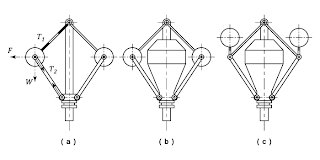
5.      Why flywheels are used in punching machines?
Use of flywheel in punching machine is due to the following reasons:
a.       It decreases the variation of speed during each cycle of punching machine.
b.      It decreases the fluctuation of speed due to difference in output and input
c.       It stores energy during idle stroke and releases during working stroke.
6.      Why flywheel is used in IC engines?
In IC engine or stem engine the energy is developed during the power stroke, no energy is developed during suction, compression and exhaust strokes in 4 stroke engine. It helps the crank shaft to run at uniform speed by performing its primary function
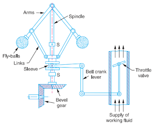
7.      What is the difference in the function of governor and a flywheel?
Governor regulates the mean speed of an engine when there are variations in load by changing the supply of working fluid. Flywheel does not maintain a constant speed. It reduces the fluctuations.
8.      Coefficient of fluctuation of speed is ------------ of maximum fluctuation of speed and the mean speed
Ratio
9.      Due to centrifugal forces acting on the rim, the flywheel arms will be subjected to ------------- stresses
Tensile
10.  Why flywheel arm are usually elliptical?
This shape helps in more section modulus for the dame weight. This results in more strength than circular section
11.  Under what consideration the shaft for a flywheel is designed?
It is designed under shear stresses produced due to the combined action of torsion and bending moment.
12.   In a flywheel, the major axis of the elliptical section of the arm is the plane of rotation. Write done the reason for this arrangement.
The arms may have to carry the full torque load due to high inertia of the flywheel when the energy input to its shaft is cut off. The arm may be assumed as a cantilever fixed at the hub and carrying the load at the rim end. This bending moment lies in the plane of rotation of the flywheel. Therefore, the major axis of the arms must be parallel to the tangential force F acting on the flywheel.
Bending moment on the arm, M = F(R-dh/2)
                                    F = t/(nR)
Where n = number of arms
Section modulus of arm, Z = (Ï€/32 )b1a12
Bending stress σb = M/Z
13.   On what basis the material of flywheel is selected?
a.       High tensile strength
b.      High fatigue strength
c.       Low shrinkage
14.  What are the advantages of having elliptical section of flywheel arm?
The flywheel arms are made of elliptical with major axis twice the minor axis. The major axis lies in the plane of rotation and provides double the resistance against bending moment.
15.   Difference between flywheel and governor
The function of a governor in engine is entirely different from that of a flywheel. It regulates the mean speed of an engine when there are variations in the load, e.g. when the load on the engine increases, it becomes necessary to increase the supply of working fluid. On the other hand, when the load decreases, less working fluid is required. The governor automatically controls the supply of working fluid to the engine with the varying load condition and keeps the mean speed within certain limits.
As discussed above, the flywheel does not maintain a constant speed; it simply reduces the fluctuation of speed. In other words, a flywheel controls the speed variations caused by the fluctuation of the engine turning moment during each cycle of operation. It does not control the speed variations caused by the varying load.
16.  Define the following terms
Coefficient of Fluctuation of Speed, coefficient of steadiness, fluctuation of energy, maximum fluctuation of energy, Coefficient of Fluctuation of Energy
Coefficient of fluctuation of speed: The difference between the maximum and minimum speeds during a cycle is called the maximum fluctuation of speed. The ratio of the maximum fluctuation of speed to the mean speed is called coefficient of fluctuation of speed.
Coefficient of steadiness: The reciprocal of coefficient of fluctuation of speed is known as coefficient of steadiness and it is denoted by m.
Fluctuation of energy, maximum fluctuation of energy: 
The fluctuation of energy may be determined by the turning moment diagram for one complete cycle of operation. Consider a turning moment diagram for a single cylinder double acting steam engine as shown in Fig.  The vertical ordinate represents the turning moment and the horizontal ordinate (abscissa) represents the crank angle.
 
A little consideration will show that the turning moment is zero when the crank angle is zero. It rises to a maximum value when crank angle reaches 90º and it is again zero when crank angle is 180º. This is shown by the curve abc in Fig. and it represents the turning moment diagram for outstroke. The curve cde is the turning moment diagram for instroke and is somewhat similar to the curve abc. Since the work done is the product of the turning moment and the angle turned, therefore the area of the turning moment diagram represents the work done per revolution. In actual practice, the engine is assumed to work against the mean resisting torque, as shown by a horizontal line AF. The height of the ordinate aA represents the mean height of the turning moment diagram. Since it is assumed that the work done by the turning moment per revolution is equal to the work done against the mean resisting torque, therefore the area of the rectangle aA Fe is proportional to the work done against the mean resisting torque. We see in Fig.  that the mean resisting torque line AF cuts the turning moment diagram at points B, C, D and E. When the crank moves from ‘a’ to ‘p’ the work done by the engine is equal to the area aBp, whereas the energy required is represented by the area aABp. In other words, the engine has done less work (equal to the area aAB) than the requirement. This amount of energy is taken fromthe flywheel and hence the speed of the flywheel decreases. Now the crank moves from p to q, the work done by the engine is equal to the area pBbCq, whereas the requirement of energy is represented by the area pBCq. Therefore the engine has done more work than the requirement. This excess work (equal to the area BbC) is stored in the flywheel and hence the speed of the flywheel increases while the crank moves from p to q.
Similarly when the crank moves from q to r, more work is taken from the engine than is developed. This loss of work is represented by the area CcD. To supply this loss, the flywheel gives up some of its energy and thus the speed decreases while the crank moves from q to r. As the crank moves from r to s, excess energy is again developed given by the area DdE and the speed again increases. As the piston moves from s to e, again there is a loss of work and the speed decreases. The variations of energy above and below the mean resisting torque line are called fluctuation of energy. The areas BbC, CcD, DdE etc. represent fluctuations of energy. A little consideration will show that the engine has a maximum speed either at q or at s. This is due to the fact that the flywheel absorbs energy while the crank moves from p to q and from r to s. On the other hand, the engine has a minimum speed either at p or at r. The reason is that the flywheel gives out some of its energy when the crank moves from a to p and from q to r. The difference between the maximum and the minimum energies is known as maximum fluctuation of energy 
Coefficient of Fluctuation of Energy 
It is defined as the ratio of the maximum fluctuation of energy to the work done per cycle. It is usually denoted by CE

FlyWheel:Rotational Speed

Rotational Speed
The second factor determining the energy a flywheel stores is the rotational speed. 
 
The energy a flywheel stores is proportional to the square of the rotational speed. Therefore, if a flywheel’s speed doubles, the amount of energy it stores will quadruple.
 
Rotational speed is a factor that must be measured using a tachometer


FlyWheel: Moment of Inertia

Moment of Inertia
Newton’s Second Law of Motion states that force is equivalent to the mass of the object multiplied by its acceleration. However, this equation is different for an object that rotates. In rotation, force is replaced with torque, acceleration is replaced with rotational acceleration, and mass is replaced with the moment of inertia. Newton’s Second Law of Rotation states that torque is equivalent to the moment of inertia multiplied by rotational acceleration. The object’s mass, radius,and inertia constant
determine the moment of inertia. 
The mass and radius of a flywheel can easily be determined by weighing and measuring. However, the inertia constant of a flywheel is dependent on the shape 
.
Flywheels are usually one of two shapes: a ring with spokes or a solid disk. A ring with spokes most clearly resembles a wheel, while a solid disk looks like a CD with out a hole in the middle. 
Since flywheels usually only come in these two shapes we will only be concerned with two values of inertia constant
.
The inertia constant for a ring is 1.0 and the inertia constant for a disk is 0.5. The difference in the inertia constants is due to the fact that all of the mass in a ring is concentrated at its circumference, while the mass of a disk is evenly distributed from the center to the outside.


Other Topics

FlyWheel: Energy

Energy
When more kinetic energy can be stored in a fly wheel, the less energy needs to come from the main power source. This increases the efficiency of the mechanism’s energy output. Because a flywheel can be used in such a variety of mechanisms, the amount of energy stored in the flywheel varies. There are two factors that control the amount of energy the flywheel stores: the moment of inertia
and the rotational speed of the flywheel


FlyWheel Benefits

Benefits
Energy moving in and out of the flywheel can be used to provide temporary and constant power. A flywheel’s greatest benefit is in mechanisms where the main power source is provided in unsteady bursts. By using conservation of energy, the flywheel stores energy as it is being released from the main power source in a surge or burst. As the main source of energy decreases, the
energy stored in the flywheel is released. Mechanisms will receive an uninterrupted sup
ply of energy. Currently, flywheels are used in electrical grids to level out power surges and in cars to smooth the rapid explosions from the engine that provide power.


Introduction to Flywheels

Introduction to Flywheels
A flywheel is a rotating disk that stores energy as kinetic energy.
The faster the flywheel spins the more kinetic energy it stores. The flywheel rotates with a connecting
rod, known as the shaft. The shaft is where the energy moves in and out of the flywheel.

enginegearclutch.blogspot.in
.


Other Topics

Physics basic inventions and inventors

1.Which instrument is used to measure altitudes in aircraft's ? Audiometer Ammeter Altimeter Anemometer Explanation : ...