Continuous casting, also referred to as strand casting, is
a process used in manufacturing industry to cast a continuous length of metal. Molten
metal is cast through a mold, the casting takes the two dimensional profile of the mold
but its length is indeterminate. The casting will keep traveling downward, its length
increasing with time. New molten metal is constantly supplied to the mold, at exactly
the correct rate, to keep up with the solidifying casting. Industrial manufacture of
continuous castings is a very precisely calculated operation. Continuous casting can
produce long strands from aluminum and copper, also the process has been developed
for the production of steel.
The Process
Molten metal, from some nearby source, is poured into a
tundish.
A tundish is a container that is located above the mold, it holds the liquid metal
for the casting. This particular casting operation uses the force of gravity to fill the
mold and to help move along the continuous metal casting. The tundish is where the
operation begins and is thus located high above ground level, as much as
eighty or ninety feet. As can be seen, the continuous casting operation may require
a lot of space.
It is the job of the tundish to keep the mold filled to the right level throughout
the manufacturing operation. Since the metal casting is constantly moving through the
mold, the tundish must always be supplying the mold with more molten metal to
compensate.
The supplying of metal to the mold is not only going on throughout the entire
manufacturing operation, it must be carried out with accuracy. A control system
is employed to assist with this task. Basically the system can sense what the level of
molten metal is, knows what the level should be, and can control the pouring of the
metal from the tundish to ensure the smooth flow of the casting process.
Although the tundish can typically hold several thousand pounds of metal, it
too must be constantly supplied from the source of molten material.
The tundish also serves as the place where slag and impurities are removed from
the melt. The high melting point and reactive nature, at high temperatures, has always made
steel a difficult material to cast. When a manufacturing operation is continuously casting
steel, the reactivity of the molten steel to the environment needs to be controlled. For this
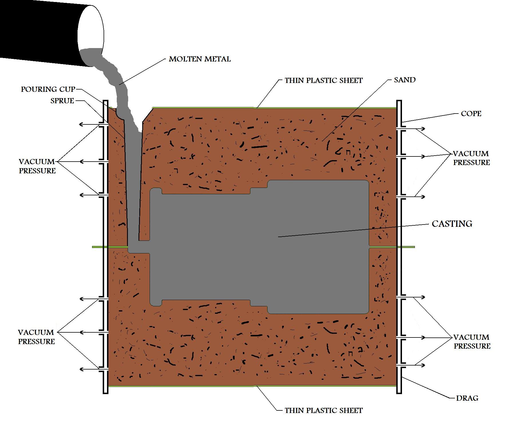
purpose, the mold entrance may be filled with an inert gas such as argon. The inert gas
will push away any other gases, such as oxygen, that may react with the metal. There is
no need to worry about the inert gas reacting with a molten metal melt, since inert gases
do not react with anything at all.
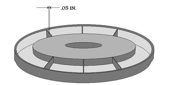
The metal casting moves quickly through the mold, in the continuous manufacture of the
metal part. The casting does not have time to solidify completely in the mold. As can be
remembered from our discussion on solidification, a metal casting will first solidify from the
mold wall, or outside of the casting, then solidification will progress inward. The mold in
the continuous casting process is water cooled, this helps speed up the solidification of the
metal casting. As stated earlier, the continuous casting does not completely harden in the
mold. It does, however, spend enough time in the water cooled mold to develop a protective
solidified skin of an adequate thickness on the outside.
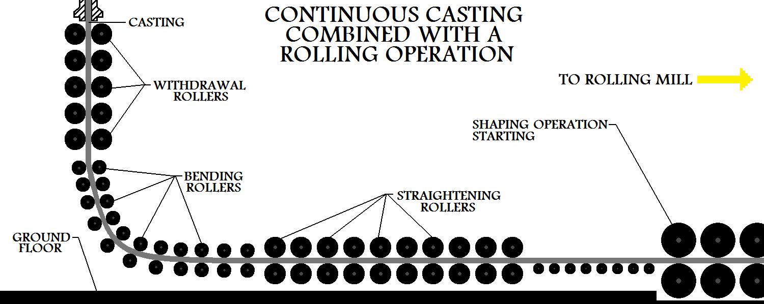
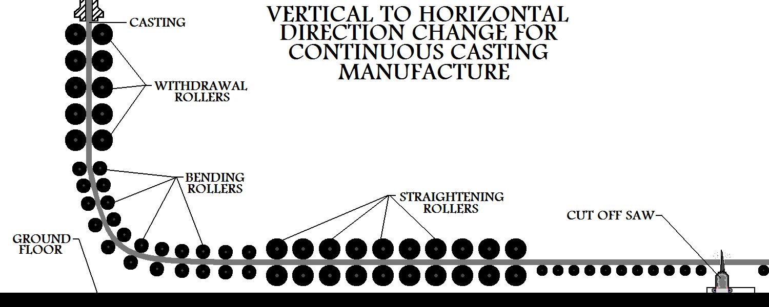
The long metal strand is moved along at a constant rate, by way of rollers. The rollers
help guide the strand and assist in the smooth flow of the metal casting out of the mold and along
its given path. A group of special rollers may be used to bend the strand to a 90 degree angle.
Then another set will be used to straighten it, once it is at that angle. Commonly used in
manufacturing industry, this process will change the direction of flow of the metal strand from
vertical to horizontal.
|
The continuous casting can now travel horizontally as far as necessary. The cutting
device, in manufacturing industry, is typically a torch or a saw. Since the metal casting does not
stop moving, the cutting device must move with the metal casting, at the same speed, as it does
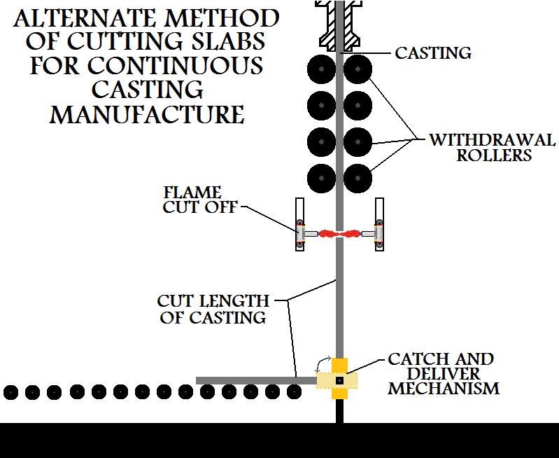
its cutting. There is another commonly used setup for cutting lengths of metal casting strand from
a continuous casting operation. This particular manufacturing setup eliminates
the need for bending and straightening rollers. It does, however, limit the length of
metal casting strand that may be produced, based in a large part on the height of the casting
floor where the mold is located.
|
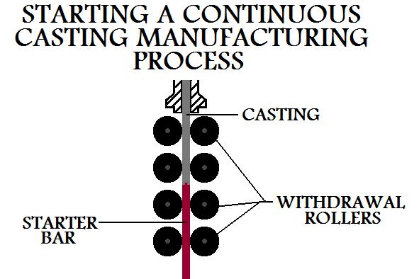
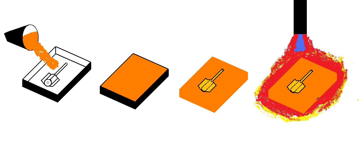
There needs to be an initial setup for a continuous casting operation, since you can not
just pour molten metal through an empty system to start off the process. To begin
continuous casting manufacture, a starter bar is placed at the bottom of the mold. Molten
material for the metal casting is poured into the mold and solidifies to the bar. The bar gives the
rollers something to grab onto initially. The rollers pull the bar, which pulls along the
continuous casting.
In the manufacture of a product, often two or more different kinds of operations may
need to be performed. Such as a metal casting operation followed by a metal forming operation. In
modern commercial industry, the continuous casting process can be integrated with metal rolling.
Do not confuse the
rolling operation with the
rolls used to guide the casting.
The rolling operation is a forming process and it will change the metal it processes.
Rolling of the metal strand, is the second manufacturing process and it must be performed
after the casting operation. Continuous casting is very convenient in that the rolling mill can be
fed directly from the continuously cast metal casting strand. The metal strand can be rolled
directly into a given cross sectional shape such as an I beam. The rate of the rolling operation
is synchronized with the speed that the continuous metal casting is produced and thus the
two operations are combined as one.
Properties And Considerations Of Manufacturing
By Continuous Casting
- Continuous casting manufacture is different from other metal casting processes, particularly
in the timing of the process. In other casting operations, the different steps to the process
such as the ladling of metal, pouring, solidification, and casting removal all take place
one at a time in a sequential order. In continuous casting manufacture, these steps are all
occurring constantly and at the same time.
- This process is used in commercial manufacture as a replacement to the
traditional process of casting ingots.
- Piping, a common problem in ingot manufacture, is eliminated with the continuous
casting process.
- Structural and chemical variations in the metal of the casting, often present in
ingots, have been eliminated. When manufacturing with the continuous metal casting process,
the casting's material will possess uniform properties.
- When employing continuous metal casting manufacture, the castings will solidify at
10 times the rate that a casting solidifies during ingot production.
- With less loss of material, cost reduction, higher productivity rate, and superior
quality of castings, continuous casting manufacture is often the choice over ingot
production.
- A continuous casting manufacturing process will take considerable resources and
planning to initiate, it will be employed in only very serious industrial operations.
Other Topics
IC engine,
Air
Standard Cycles,
Method
of Ignition,
Gear Types,
mechanical
Engineering,
Gears,
spur gears,
Worm gears,
English books,
Photoshop
tutorials,
Physics files,
Thamizh,
Manufacturing,
Gears pdf,
Computer
science,
Harry
potter,
Best
100 english books,
Face Gears,
IC
engine,
Metal
Casting,
Sand
casting,
SAND
Casting Quiz,
Casting
patterns quiz,
Sand
Casting Process,
Patterns,
Mechnical
Previous Years Gate Question Papers ,
Mechanical-old-question-paper,
Core
and Core Box,
Shell
Moulding,
Permanent
mold casting,
Investment
Casting,
Die
Casting,
Centrifugal
Casting,
Workshop
Technology Quiz,
Milling
Quiz,
Metal
Quiz,
Mechanical
Process Quiz,
Chemically
Bonded Molding Systems,
Unbonded
Sand Processes,
Green
Sand Molding,
Gases
Iin Metal Casting,
Plaster
Mold Casting,
Ceramic
Mold Casting,
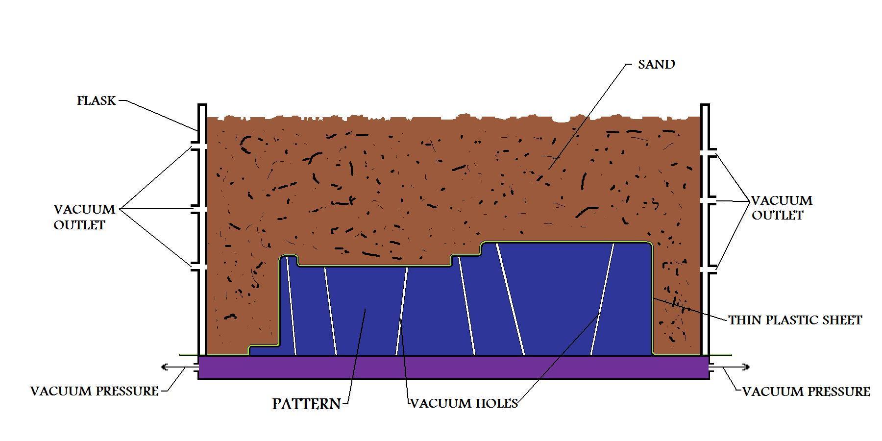
Vacuum
Casting,
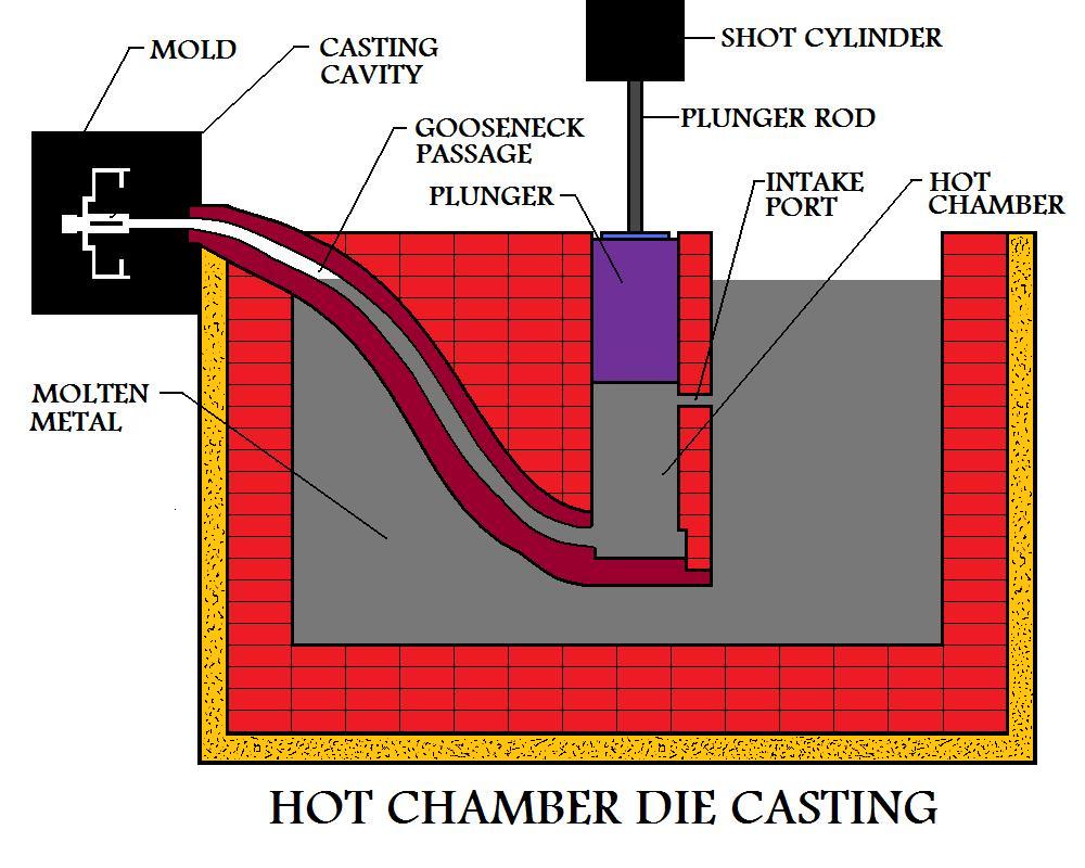
Hot
Chamber Die Casting,