Thursday, 21 November 2013

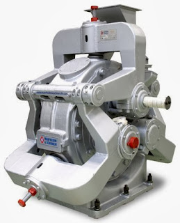
Disc mill type Pulverizer

Disc mill type Pulverizer- Economic pulverizing of plastic granules          
Our pulverizing systems, are high capacity systems for the profitable pulverizing of thermoplastic and other heat sensitive materials such as LDPE, LLDPE, MDPE and HDPE, as well as other heat sensitive thermoplastics such as PP and EVA without the added cooling of nitrogen.

Our  pulverizing systems produce quality powders with excellent flow properties and bulk densities nd are mainly used for the following applications:

    Pulverization of rigid PVC (pipe and profile granules)
    Pulverization of PE for Rotomolding
    Pulverization of PE for textile and metal coating
    Pulverization of PP for fiber manufacture
    Pulverization of compounds for floor coverings

This Pulverize machine is simple, clearly arranged and operates with a further developed screening machine. The advantages for the customer are obvious:

    Quality powders with best possible flow properties and high bulk density
    High throughput capacity at low specific power consumption
    Fully automatic, continuous operation

Low demands on operating personnel


Other Topics

Concept of Rotational Moulding with Pulverizing Machine

Concept of Rotational Moulding with Pulverizing Machine

Rotational Moulding needs resin in pulverized form. The particle size, shape and particle size distribution is measure of powder quality. Powder quality plays a very important role in rotational moulding.

Following are the resultant effects of the good quality powder:

    Optimization of the charge weight to meet rising competition
    Improved finish an color of the product
    Reduced fusion time
    Multi layered and foamed tanks

Realizing the extraordinary needs of the rotational molders engineers at N.A. Group of Companies set out to expand the next generation pulveriser. To attain the above objective pulveriser must have following features.

    Ability and control to give uniform and consistent Powder Quality
    Power required should be low
    Cooling of grinding element must be sufficient and effective
    High out put
    Minimum down time
    Ability to run the machine un attended
    All system protections so that down time is Low

Easy to clean , user friendly operation


Other Topics

The Plastic Granulator

The Plastic Granulator


The Plastic Granulator is the most universal type of pulverizer used with plastic recycling. It is capable of turning jugs, large bottles, and other plastic products into flakes, which are referred to as granules. These granules are then sold to manufacturers in order to be remolded into new products.

Plastic Granulator is basically a large electric motor with a rotor. The motor rotates the rotor, which contains cutting blades. The motor, the rotor and the blades are all located inside a closed chamber in which the plastic is positioned. The blades and the chambers of plastic granulators are accessible in different sizes and shapes with the purpose of assemble different needs.


There is also a screen situated inside the chamber of plastic granulator. This screen sifts the plastic in order to ensure all of the parts are small enough to be reprocessed, which normally ranges from .125 to .375 inches. If any parts that are too large to in shape through the screen are processed once more within the plastic granulator.


The efficiency of a plastic granulator is based upon how a large amount plastic it can shred in one hour, which is referred to as its pounds per hour rating. For engineering recycling purposes, the plastic granulator needs to be very large to process considerable amounts of plastic. There are, however, smaller plastic granulators available for home utilization. No matter the size, Plastic Granulators can be dangerous. Therefore, it is essential to always follow the manufacturer's instructions when using a plastic granulator.


A plastic granulator also must be kept clean to remain capable. Generally, the screen situated inside the chamber of plastic granulator is cleaned out after each large processing. Otherwise, pieces of plastic can get stuck in the screening and stop other granules from falling through. The blades of the plastic granulator also require being wiped dirt free and oiled to maintain plastic granulator running efficiently.


Other Topics

Advantages of Plastic Pulveriser

Advantages of Plastic Pulveriser or Pulverizer in engineering reprocessing are as follows:

    Low residence time means lower thermal stress on the process material
    Heavy-duty construction for longevity
    Ease of maintenance
    Ease of operation
    Full inventory of replacement parts
    Can cool the processing of heat- sensitivity materials by water cycle system
    High through put capabilities
    Cost effective operation
    Low specific power consumption
    Powder quality according to specification

The models of pulverizing machine ensure the production of pulverized material from plastic granules for the manufacturing of high quality final products. Our Plastic pulverizer can pulverize LDPE, LLDPE, HDPE and various thermoplastic materials and can offer to develop other kinds of pulverize for different materials on request.

Pulverizers are available in various configurations like single mill, double mill, horizontals mill with various designs, sizes and shapes of pulverizer blades.

The Pulverizer constitutes of high quality, maintenance-free, efficient components, like the Pulverizer Blade. The Pulverizers have very special designs and are being approved by our in-house quality control and testing departments after going through rigorous tests and routine check-up procedures.


Other Topics

Plastic Pulverizer

                
Plastic Pulverizer     
In plastic reprocessing after the types of plastic separated is a Mechanical processing to run the plastic through the Pulverizer. Pulverizer or Pulveriser crushes the plastic into tiny shreds or granules. Plastic pulverizer is the particular equipment for recycling disused insignificant materials in producing and grinding heat-sensitivity plastic such as PVC.

Pulverizer includes high output units which can be equipped with automatic temperature control. The material to be pulverized is fed centrally between a fixed and a high speed rotating pulveriser disc with centrifugal effect carrying the material through the processing zone before being discharged from the machine pneumatically.

Several different types of pulverizer machines are used to smash down other materials, such as rock, glass, wood, metals, and cement. When it comes to plastic, the three primary types of pulverizers are granulators, shredders, and ring mills.


A granulator operates thousands of evenly spaced blades in order to shred or granule the plastic into finely pulverized objects. After it is pulverized, it can be melted and reformed.

A shredder is similar to a granulator in that it contains evenly spaced blades, though these blades cut the plastic into strips. Some cut both vertically and horizontally in order to produce square shaped plastic pieces.

A ring mill, on the other hand, has a large, steel rolling blade. This blade chops and grinds the plastic that is placed inside the roller. After it has been ground up to the desired size, it falls through the small holes located beneath the rolling blade.Fig shows Ring mill


http://enginegearclutch.blogspot.in/

http://enginegearclutch.blogspot.in/


Other Topics

Pulverizer

What is Pulverizer?          

Pulverizer machines are used to smash materials into tiny shards or granules. Pulverizer machines can crush all types of items, including plastic, glass, aluminum, concrete, coal, rock, resin, tires, and medical waste. Pulverizer machines come in a number of different forms. Hammer mills, ring mills, double roll crushers, granulators, impactors, and shredders are all forms of pulverizer machines. Pulverizer is used in plastic industry for Plastics Pulverizing Including PVC Recycling, Rotational Molding, Compounding and Master batching.

The Naroto range of pulverizer ensures the production of pulverized material from plastic granules for the manufacturing of high quality final products. Pulverizer can pulverize LDPE, LLDPE, HDPE and various thermoplastic materials and other kinds of pulverize for different materials.

Pulverisers has fully automatic operations with predetermined sequence of operations such as Automatic granule lifter, Automatic on and off feeder, Automatic controls of mill temperature etc. The Pulverizer constitutes of high quality, maintenance-free, efficient components.

Pulverizers are available in various configurations like Single Mill Pulverizer, Twin Mill Pulverizer (Dual Mill Pulverizer) with various designs, sizes and shapes of pulverizer blades.

In Plastic Industry, there are need for advanced technology and improvements, reduced maintenance and higher production rates. We incorporated these requirements into all our pulverizing machines. We are supplying the latest in pulverizing technology and auxiliary equipment to the rotational molding industry.

The steadily increasing demand for powders of plastic, rubber,

or minerals of any kind as well as the constantly expanding quality requirements with regards to flow ability, bulk density, particle size distribution and grain structure, pulverizing systems is the best solution. 

http://enginegearclutch.blogspot.in/


Other Topics

Thermal Power Plant


Thermal Power Plant Lay out :


The above diagram is the lay out of a simplified thermal power plant and the below is also diagram of a thermal power plant.

The above diagram shows the simplest arrangement of Coal fired (Thermal) power plant.


Main parts of the plant are
1. Coal conveyor 2. Stoker 3. Pulverizer 4. Boiler 5. Coal ash 6. Air preheater 7. Electrostatic precipitator 8. Smoke stack 9. Turbine 10. Condenser 11. Transformers 12. Cooling towers
13. Generator 14. High - votge power lines

Basic Operation :A thermal power plant basically works on Rankine cycle.
Coal conveyor : This is a belt type of arrangement.With this coal is transported from coal storage place in power plant to the place near by boiler.
Stoker : The coal which is brought near by boiler has to put in boiler furnance for combustion.This stoker is a mechanical device for feeding coal to a furnace.

Pulverizer : The coal is put in the boiler after pulverization.For this pulverizer is used.A pulverizer is a device for grinding coal for combustion in a furnace in a power plant.

Types of Pulverizers :
Ball and Tube Mill Ball mill is a pulverizer that consists of a horizontal rotating cylinder, up to three diameters in length, containing a charge of tumbling or cascading steel balls, pebbles, or rods.
Tube mill is a revolving cylinder of up to five diameters in length used for fine pulverization of ore, rock, and other such materials; the material, mixed with water, is fed into the chamber from one end, and passes out the other end as slime.
Ring and Ball
This type consists of two rings separated by a series of large balls. The lower ring rotates, while the upper ring presses down on the balls via a set of spring and adjuster assemblies. Coal is introduced into the center or side of the pulverizer (depending on the design) and is ground as the lower ring rotates causing the balls to orbit between the upper and lower rings. The coal is carried out of the mill by the flow of air moving through it. The size of the coal particals released from the grinding section of the mill is determined by a classifer separator. These mills are typically produced by B&W (Babcock and Wilcox).

Boiler : Now that pulverized coal is put in boiler furnance.Boiler is an enclosed vessel in which water is heated and circulated until the water is turned in to steam at the required pressure.

Coal is burned inside the combustion chamber of boiler.The products of combustion are nothing but gases.These gases which are at high temperature vaporize the water inside the boiler to steam.Some times this steam is further heated in a superheater as higher the steam pressure and temperature the greater efficiency the engine will have in converting the heat in steam in to mechanical work. This steam at high pressure and tempeture is used directly as a heating medium, or as the working fluid in a prime mover to convert thermal energy to mechanical work, which in turn may be converted to electrical energy. Although other fluids are sometimes used for these purposes, water is by far the most common because of its economy and suitable thermodynamic characteristics.

Classification of Boilers 
Bolilers are classified as Fire tube boilers : In fire tube boilers hot gases are passed through the tubes and water surrounds these tubes. These are simple,compact and rugged in construction.Depending on whether the tubes are vertical or horizontal these are further classified as vertical and horizontal tube boilers.In this since the water volume is more,circulation will be poor.So they can't meet quickly the changes in steam demand.High pressures of steam are not possible,maximum pressure that can be attained is about 17.5kg/sq cm.Due to large quantity of water in the drain it requires more time for steam raising.The steam attained is generally wet,economical for low pressures.The outut of the boiler is also limited.

Water tube boilers : In these boilers water is inside the tubes and hot gases are outside the tubes.They consists of drums and tubes.They may contain any number of drums (you can see 2 drums in fig).Feed water enters the boiler to one drum (here it is drum below the boiler).This water circulates through the tubes connected external to drums.Hot gases which surrounds these tubes wil convert the water in tubes in to steam.This steam is passed through tubes and collected at the top of the drum since it is of light weight.So the drums store steam and water (upper drum).The entire steam is collected in one drum and it is taken out from there (see in laout fig).As the movement of water in the water tubes is high, so rate of heat transfer also becomes high resulting in greater efficiency.They produce high pressure , easily accessible and can respond quickly to changes in steam demand.These are also classified as vertical,horizontal and inclined tube depending on the arrangement of the tubes.These are of less weight and less liable to explosion.Large heating surfaces can be obtained by use of large number of tubes.We can attain pressure as high as 125 kg/sq cm and temperatures from 315 to 575 centigrade.
Superheater : Most of the modern boliers are having superheater and reheater arrangement. Superheater is a component of a steam-generating unit in which steam, after it has left the boiler drum, is heated above its saturation temperature. The amount of superheat added to the steam is influenced by the location, arrangement, and amount of superheater surface installed, as well as the rating of the boiler. The superheater may consist of one or more stages of tube banks arranged to effectively transfer heat from the products of combustion.Superheaters are classified as convection , radiant or combination of these.

Reheater : Some of the heat of superheated steam is used to rotate the turbine where it loses some of its energy.Reheater is also steam boiler component in which heat is added to this intermediate-pressure steam, which has given up some of its energy in expansion through the high-pressure turbine. The steam after reheating is used to rotate the second steam turbine (see Layout fig) where the heat is converted to mechanical energy.This mechanical energy is used to run the alternator, which is coupled to turbine , there by generating elecrical energy.

Condenser : Steam after rotating staem turbine comes to condenser.Condenser refers here to the shell and tube heat exchanger (or surface condenser) installed at the outlet of every steam turbine in Thermal power stations of utility companies generally. These condensers are heat exchangers which convert steam from its gaseous to its liquid state, also known as phase transition. In so doing, the latent heat of steam is given out inside the condenser. Where water is in short supply an air cooled condenser is often used. An air cooled condenser is however significantly more expensive and cannot achieve as low a steam turbine backpressure (and therefore less efficient) as a surface condenser.

The purpose is to condense the outlet (or exhaust) steam from steam turbine to obtain maximum efficiencyand also to get the condensed steam in the form of pure water, otherwise known as condensate, back to steam generator or (boiler) as boiler feed water.

Why it is required ?

The steam turbine itself is a device to convert the heat in steam to mechanical power. The difference between the heat of steam per unit weight at the inlet to turbine and the heat of steam per unit weight at the outlet to turbine represents the heat given out (or heat drop) in the steam turbine which is converted to mechanical power. The heat drop per unit weight of steam is also measured by the word enthalpy drop. Therefore the more the conversion of heat per pound (or kilogram) of steam to mechanical power in the turbine, the better is its performance or otherwise known as efficiency. By condensing the exhaust steam of turbine, the exhaust pressure is brought down below atmospheric pressure from above atmospheric pressure, increasing the steam pressure drop between inlet and exhaust of steam turbine. This further reduction in exhaust pressure gives out more heat per unit weight of steam input to the steam turbine, for conversion to mechanical power. Most of the heat liberated due to condensing, i.e., latent heat of steam, is carried away by the cooling medium. (water inside tubes in a surface condenser, or droplets in a spray condenser (Heller system) or air around tubes in an air-cooled condenser).

Condensers are classified as (i) Jet condensers or contact condensers (ii) Surface condensers.
In jet condensers the steam to be condensed mixes with the cooling water and the temperature of the condensate and the cooling water is same when leaving the condenser; and the condensate can't be recovered for use as feed water to the boiler; heat transfer is by direct conduction.

In surface condensers there is no direct contact between the steam to be condensed and the circulating cooling water. There is a wall interposed between them through heat must be convectively transferred.The temperature of the condensate may be higher than the temperature of the cooling water at outlet and the condnsate is recovered as feed water to the boiler.Both the cooling water and the condensate are separetely with drawn.Because of this advantage surface condensers are used in thermal power plants.Final output of condenser is water at low temperature is passed to high pressure feed water heater,it is heated and again passed as feed water to the boiler.Since we are passing water at high temperature as feed water the temperature inside the boiler does not dcrease and boiler efficincy also maintained.

Cooling Towers :The condensate (water) formed in the condeser after condensation is initially at high temperature.This hot water is passed to cooling towers.It is a tower- or building-like device in which atmospheric air (the heat receiver) circulates in direct or indirect contact with warmer water (the heat source) and the water is thereby cooled (see illustration). A cooling tower may serve as the heat sink in a conventional thermodynamic process, such as refrigeration or steam power generation, and when it is convenient or desirable to make final heat rejection to atmospheric air. Water, acting as the heat-transfer fluid, gives up heat to atmospheric air, and thus cooled, is recirculated through the system, affording economical operation of the process.

Two basic types of cooling towers are commonly used. One transfers the heat from warmer water to cooler air mainly by an evaporation heat-transfer process and is known as the evaporative or wet cooling tower.

Evaporative cooling towers are classified according to the means employed for producing air circulation through them:atmospheric, natural draft, and mechanical draft. The other transfers the heat from warmer water to cooler air by a sensible heat-transfer process and is known as the nonevaporative or dry cooling tower.

Nonevaporative cooling towers are classified as air-cooled condensers and as air-cooled heat exchangers, and are further classified by the means used for producing air circulation through them. These two basic types are sometimes combined, with the two cooling processes generally used in parallel or separately, and are then known as wet-dry cooling towers.

Evaluation of cooling tower performance is based on cooling of a specified quantity of water through a given range and to a specified temperature approach to the wet-bulb or dry-bulb temperature for which the tower is designed. Because exact design conditions are rarely experienced in operation, estimated performance curves are frequently prepared for a specific installation, and provide a means for comparing the measured performance with design conditions.

Economiser : Flue gases coming out of the boiler carry lot of heat.Function of economiser is to recover some of the heat from the heat carried away in the flue gases up the chimney and utilize for heating the feed water to the boiler.It is placed in the passage of flue gases in between the exit from the boiler and the entry to the chimney.The use of economiser results in saving in coal consumption , increase in steaming rate and high boiler efficiency but needs extra investment and increase in maintenance costs and floor area required for the plant.This is used in all modern plants.In this a large number of small diameter thin walled tubes are placed between two headers.Feed water enters the tube through one header and leaves through the other.The flue gases flow out side the tubes usually in counter flow.

Air preheater : The remaining heat of flue gases is utilised by air preheater.It is a device used in steam boilers to transfer heat from the flue gases to the combustion air before the air enters the furnace. Also known as air heater; air-heating system. It is not shown in the lay out.But it is kept at a place near by where the air enters in to the boiler.
The purpose of the air preheater is to recover the heat from the flue gas from the boiler to improve boiler efficiency by burning warm air which increases combustion efficiency, and reducing useful heat lost from the flue. As a consequence, the gases are also sent to the chimney or stack at a lower temperature, allowing simplified design of the ducting and stack. It also allows control over the temperature of gases leaving the stack (to meet emissions regulations, for example).After extracting heat flue gases are passed to elctrostatic precipitator.
Electrostatic precipitator : It is a device which removes dust or other finely divided particles from flue gases by charging the particles inductively with an electric field, then attracting them to highly charged collector plates. Also known as precipitator. The process depends on two steps. In the first step the suspension passes through an electric discharge (corona discharge) area where ionization of the gas occurs. The ions produced collide with the suspended particles and confer on them an electric charge. The charged particles drift toward an electrode of opposite sign and are deposited on the electrode where their electric charge is neutralized. The phenomenon would be more correctly designated as electrodeposition from the gas phase.
The use of electrostatic precipitators has become common in numerous industrial applications. Among the advantages of the electrostatic precipitator are its ability to handle large volumes of gas, at elevated temperatures if necessary, with a reasonably small pressure drop, and the removal of particles in the micrometer range. Some of the usual applications are: (1) removal of dirt from flue gases in steam plants; (2) cleaning of air to remove fungi and bacteria in establishments producing antibiotics and other drugs, and in operating rooms; (3) cleaning of air in ventilation and air conditioning systems; (4) removal of oil mists in machine shops and acid mists in chemical process plants; (5) cleaning of blast furnace gases; (6) recovery of valuable materials such as oxides of copper, lead, and tin; and (7) separation of rutile from zirconium sand.
Smoke stack :A chimney is a system for venting hot flue gases or smoke from a boiler, stove, furnace orfireplace to the outside atmosphere. They are typically almost vertical to ensure that the hot gases flow smoothly, drawing air into the combustion through the chimney effect (also known as the stack effect). The space inside a chimney is called a flue. Chimneys may be found in buildings, steam locomotives and ships. In the US, the term smokestack (colloquially, stack) is also used when referring to locomotive chimneys. The term funnel is generally used for ship chimneys and sometimes used to refer to locomotive chimneys.Chimneys are tall to increase their draw of air for combustion and to disperse pollutants in the flue gases over a greater area so as to reduce the pollutant concentrations in compliance with regulatory or other limits.

Generator : An alternator is an electromechanical device that converts mechanical energy to alternating current electrical energy. Most alternators use a rotating magnetic field. Different geometries - such as a linear alternator for use with stirling engines - are also occasionally used. In principle, any AC generator can be called an alternator, but usually the word refers to small rotating machines driven by automotive and other internal combustion engines.

Transformers :It is a device that transfers electric energy from one alternating-current circuit to one or more other circuits, either increasing (stepping up) or reducing (stepping down) the voltage. Uses for transformers include reducing the line voltage to operate low-voltage devices (doorbells or toy electric trains) and raising the voltage from electric generators so that electric power can be transmitted over long distances. Transformers act through electromagnetic induction; current in the primary coil induces current in the secondary coil. The secondary voltage is calculated by multiplying the primary voltage by the ratio of the number of turns in the secondary coil to that in the primary.

Monday, 18 November 2013

Stability of Governors

A governor is said to be stable when for every speed within the working range there is a definite configuration i.e. there is only one radius of rotation of the governor balls at which the governor is in equilibrium.
For a stable governor, if the equilibrium speed increases, the radius of governor balls must also increase. 


Inertia Governors

This works on a different principle. The governor balls are arranged so that the inertia forces caused by angular acceleration or retardation of the governor shaft tend to alter their positions. The amount of the displacement of the balls is controlled by springs and
the governor mechanism to alter the supply of energ y to the engine. 
 
The advantage of this type of governor is that the positions of the balls are affected by
the rate of change of speed of the governor shaft.Consequently, a more rapid response
to a change of load is obtained, since the action of the governor is due to acceleration
and not to a finite change of speed. The advantageis offset, however, by the practical
difficulty of arranging for a complete balance of the revolving parts of the governor. For
this reason centrifugal governors are much more frequently used. 


Inertia Governors


Centrifugal Governors

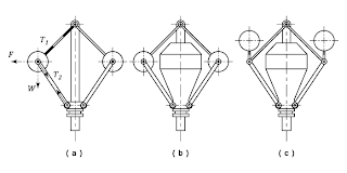
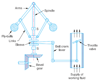
The centrifugal governors are based on the balancing of centrifugal force on the rotating balls by an equal and opposite radial force, known as the controlling force* .It consists of two balls of equal mass, which are attached to the arms as shown in Fig . These balls are known as governor balls or fly balls.The balls revolve with a spindle, which is driven by the engine through bevel gears. The upper ends of the arms are pivoted to the spindle, so that the balls may rise up or fall down as they revolve about the vertical axis. The sleeve revolves with the spindle; but can slide up and down. The balls and the sleeve rises when the spindle speed increases, and falls when the speed decreases. In order to limit the travel of the sleeve in upward and downward directions, two stops S,S are provided on the spindle.

The sleeve is connected by a bell crank lever to a throttle valve. The supply of the working fluid decreases when the sleeve rises and increaseswhen it falls. When the load on the engine increases, the engine and the governor speed decreases. This results in the decrease of centrifugal force on the balls. Hence the balls move inwards and the sleeve moves downwards. The downward movement of the sleeve operates a throttle valve at the other end of the bell crank lever to increase the supply of working fluid and thus the engine speed is increased.

Hence, the extra power output is provided to balance the increased load. When the load on the engine decreases, the engine and the governor speed increases, which results in the increase of centrifugal force on the balls. Thus the balls move outwards and the sleeve rises upwards. This upward movement of the sleeve reduces the supply of the working fluid and hence the speed is decreased. Hence, the power output is reduced.


http://enginegearclutch.blogspot.in/


Other Topics

Types of Governors

Governors

Flywheel which minimizes fluctuations of speed with
in the cycle but it cannot minimize fluctuations due to load variation. This means flyw
heel does not exercise any control over mean speed of the engine. To minimize fluctuat
ions in the mean speed which may occur due to load variation, governor is used. The
governor has no influence over cyclic speed fluctuations but it controls the mean speed o
ver a long period during which load on the engine may vary. 
 
The function of governor is to increase the supply of working fluid going to the prime- mover when the load on the prime-mover increases and to decrease the supply when the load decreases so as to keep the speed of the prime-mover almost constant at different loads.
 
Example: when the load on an engine increases, its speed decreases, therefore it becomes necessary to increase the supply of working fluid. On the other hand, when the load on the engine decreases, its speed increases and hence less working fluid is required.
When there is change in load, variation in speed also takes place then governor operates a regulatory control and adjusts the fuel supply to maintain the mean speed nearly constant. Therefore, the governor automatically regulates through linkages, the energy supply to the engine as demanded by variation of load so that the engine speed is maintained nearly constant. 


Wednesday, 13 November 2013

Flywheel: FACTOR

Maintenance:
Service- and maintenance works of the rotating converter can be done by every trained technician. A static converter can only be maintained from a specialist from the supplier/OEM. This can influence the service cost significantly.

MTBF-value:
The MTBF-Value (meantime between failure) of rotary converter is above 50.000 hrs. The MTBF of static converters is significanly lower due to the higher number of parts and electronic components.

Spares:
Spares for rotary converter are available in almost every country of the world.

Grid loading effect:
When planning static systems, you have to consider, that because of current and voltage interferences caused by static converters the Mains transformer has to be oversized by about 20%. Further on only such consumer can be connected to the transformer which are not influenced by the interferences. (Problems with UPS or diesel gen sets).

Efficiency:
The efficiencies of rotary converter and static converters are almost the same. The additional losses caused by the inverters’s harmonics are not included.

Distortion factor:
The intensity of harmonics of rotary converters is much lower than those from static converters.

Suppression of radio interference:
Suppression acc. N and K acc. VDE 0875 or MIL-standard can be fulfilled by rotary converter. Static converter already have problems with N acc. VDE 0875.

Input power factor:
The power factor is automatically controlled within the range of 0.9 to 1.0 (reactive load supply) at 50% to 100% of nominal load. Static converter consume reactive load (cos phi 0,75 - 0,85) and therby require a capacitor bank.

Overload:
Rotary converter have better overload endurability than static converter.

Shock load response:
By fast regulating the voltage at shock load often requests an enlargement of the system of static converter. Rotary converter have the capability to endure peak values of shock loads of 20 times nominal current (one half wave) or 3 times nominal current for several seconds.

Overcurrent discrimination:
The request operating static converter systems without fuses is not possible or just under certain conditions. Current peaks up to 40x nominal current for one half wave are not seldom for static converters. To obtain a selectivity highest care is necessary when selecting fuses. The installation efforts for static converters is much higher than for rotary converters.

Indirect coupling (Galvanic separation):
An indirect coupling is provided only by rotary converter.

Voltage peaks and EMP, NEMP:
Electronic parts are more responsive against voltage peaks and high magnetic fields than windings are.

Shock:
Shock proof systems with static converters are only limited practicable.


Other Topics

IC engine,  Method of Ignition,  mechanical Engineering, English books,Photoshop tutorials,Harry potter,Best 100 english books,IC engine,Metal Casting,Mechnical Previous Years Gate Question Papers ,Mechanical-old-question-paper,Milling Quiz,Forging Quiz,Cold Extrusion,Hot Extrusion,CLutch,Dry Clutch,Wet Clutch,Introduction to Flywheel,Flywheel Benefits,FlyWheel: Energy,FlyWheel: Moment of Inertia,FlyWheel:Rotational Speed,Important questions and answers on Design of Flywheel


Physics basic inventions and inventors

1.Which instrument is used to measure altitudes in aircraft's ? Audiometer Ammeter Altimeter Anemometer Explanation : ...