Thermal Power Plant Lay out :

The above diagram is the lay out of a simplified thermal power plant and the below is also diagram of a thermal power plant.

The above diagram shows the simplest arrangement of Coal fired (Thermal) power plant.

Main parts of the plant are
1. Coal conveyor
2. Stoker
3. Pulverizer
4. Boiler
5. Coal ash
6. Air preheater
7. Electrostatic precipitator
8. Smoke stack
9. Turbine
10. Condenser
11. Transformers
12. Cooling towers
13. Generator
14. High - votge power lines
Basic Operation :A thermal power plant basically works on
Rankine cycle.
Coal conveyor : This
is a belt type of arrangement.With this coal is transported from coal
storage place in power plant to the place near by boiler.
Stoker : The
coal which is brought near by boiler has to put in boiler furnance for
combustion.This stoker is a mechanical device for feeding coal to a
furnace.
Pulverizer :
The coal is put in the boiler after pulverization.For this pulverizer
is used.A pulverizer is a device for grinding coal for combustion in a
furnace in a power plant.
Types of Pulverizers :
Ball and Tube Mill Ball mill is a
pulverizer that consists of a horizontal rotating cylinder, up to three
diameters in length, containing a charge of tumbling or cascading steel
balls, pebbles, or rods.
Tube mill is a revolving cylinder of up to five diameters in length used
for fine pulverization of ore, rock, and other such materials; the
material, mixed with water, is fed into the chamber from one end, and
passes out the other end as slime.
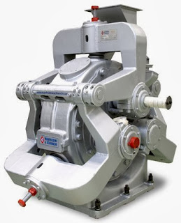
Ring and Ball
This type consists of two rings separated by a series of large balls.
The lower ring rotates, while the upper ring presses down on the balls
via a set of spring and adjuster assemblies. Coal is introduced into the
center or side of the pulverizer (depending on the design) and is
ground as the lower ring rotates causing the balls to orbit between the
upper and lower rings. The coal is carried out of the mill by the flow
of air moving through it. The size of the coal particals released from
the grinding section of the mill is determined by a classifer separator.
These mills are typically produced by B&W (Babcock and Wilcox).
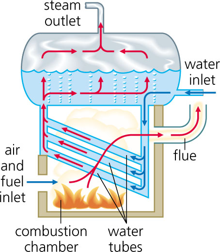
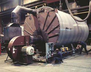
Boiler : Now that pulverized coal is put in boiler furnance.Boiler is an enclosed vessel in which water is heated and circulated until the water is turned in to steam at the required pressure.
Coal is burned inside the combustion chamber of boiler.The products of
combustion are nothing but gases.These gases which are at high
temperature vaporize the water inside the boiler to steam.Some times
this steam is further heated in a superheater as
higher the steam pressure and temperature the greater efficiency the
engine will have in converting the heat in steam in to mechanical work.
This steam at high pressure and tempeture is used directly as a heating
medium, or as the working fluid in a prime mover to convert thermal
energy to mechanical work, which in turn may be converted to electrical
energy. Although other fluids are sometimes used for these purposes,
water is by far the most common because of its economy and suitable
thermodynamic characteristics.
Classification of Boilers
Bolilers are classified as
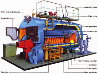
 Fire tube boilers :
 In
fire tube boilers hot gases are passed through the tubes and water
surrounds these tubes. These are simple,compact and rugged in
construction.Depending on whether the tubes are vertical or horizontal
these are further classified as vertical and horizontal tube boilers.In
this since the water volume is more,circulation will be poor.So they
can't meet quickly the changes in steam demand.High pressures of steam
are not possible,maximum pressure that can be attained is about
17.5kg/sq cm.Due to large quantity of water in the drain it requires
more time for steam raising.The steam attained is generally
wet,economical for low pressures.The outut of the boiler is also
limited.
Water tube boilers : In these boilers water is inside the tubes and hot gases are outside the tubes.They consists of drums and
 tubes.They
may contain any number of drums (you can see 2 drums in fig).Feed water
enters the boiler to one drum (here it is drum below the boiler).This
water circulates through the tubes connected external to drums.Hot gases
which surrounds these tubes wil convert the water in tubes in to
steam.This steam is passed through tubes and collected at the top of the
drum since it is of light weight.So the drums store steam and water
(upper drum).The entire steam is collected in one drum and it is taken
out from there (see in laout fig).As the movement of water in the water
tubes is high, so rate of heat transfer also becomes high resulting in
greater efficiency.They produce high pressure , easily accessible and
can respond quickly to changes in steam demand.These are also classified
as vertical,horizontal and inclined tube depending on the arrangement
of the tubes.These are of less weight and less liable to explosion.Large
heating surfaces can be obtained by use of large number of tubes.We can
attain pressure as high as 125 kg/sq cm and temperatures from 315 to
575 centigrade.
Superheater : Most of the modern boliers are having superheater and reheater arrangement. Superheater is a component
of a steam-generating unit in which steam, after it has left the boiler
drum, is heated above its saturation temperature. The amount of
superheat added to the steam is influenced by the location, arrangement,
and amount of superheater surface installed, as well as the rating of
the boiler. The superheater may consist of one or more stages of tube
banks arranged to effectively transfer heat from the products of
combustion.Superheaters are classified as convection , radiant or
combination of these.
Reheater : Some of the heat of superheated steam is used to rotate the turbine where it loses some of its energy.Reheater is also steam
boiler component in which heat is added to this intermediate-pressure
steam, which has given up some of its energy in expansion through the
high-pressure turbine. The steam after reheating is used to rotate the
second steam turbine (see Layout fig) where the heat is converted to
mechanical energy.This mechanical energy is used to run the alternator,
which is coupled to turbine , there by generating elecrical energy.
Condenser : Steam
after rotating staem turbine comes to condenser.Condenser refers here
to the shell and tube heat exchanger (or surface condenser) installed at
the outlet of every steam turbine in Thermal power stations of utility
companies generally. These condensers are heat exchangers which convert
steam from its gaseous to its liquid state, also known as phase
transition. In so doing, the latent heat of steam is given out inside
the condenser. Where water is in short supply an air cooled condenser is
often used. An air cooled condenser is however significantly more
expensive and cannot achieve as low a steam turbine backpressure (and
therefore less efficient) as a surface condenser.
The purpose is to condense the outlet (or exhaust) steam from steam turbine to obtain maximum efficiencyand
also to get the condensed steam in the form of pure water, otherwise
known as condensate, back to steam generator or (boiler) as boiler feed
water.
Why it is required ?
The steam turbine itself is a device to convert the heat in steam to
mechanical power. The difference between the heat of steam per unit
weight at the inlet to turbine and the heat of steam per unit weight at
the outlet to turbine represents the heat given out (or heat drop) in
the steam turbine which is converted to mechanical power. The heat drop
per unit weight of steam is also measured by the word enthalpy drop.
Therefore the more the conversion of heat per pound (or kilogram) of
steam to mechanical power in the turbine, the better is its performance
or otherwise known as efficiency. By condensing the exhaust steam of
turbine, the exhaust pressure is brought down below atmospheric pressure
from above atmospheric pressure, increasing the steam pressure drop
between inlet and exhaust of steam turbine. This further reduction in
exhaust pressure gives out more heat per unit weight of steam input to
the steam turbine, for conversion to mechanical power. Most of the heat
liberated due to condensing, i.e., latent heat of steam, is carried away
by the cooling medium. (water inside tubes in a surface condenser, or
droplets in a spray condenser (Heller system) or air around tubes in an
air-cooled condenser).
Condensers are
classified as (i) Jet condensers or contact condensers (ii) Surface condensers.
In jet condensers the
steam to be condensed mixes with the cooling water and the temperature
of the condensate and the cooling water is same when leaving the
condenser; and the condensate can't be recovered for use as feed water
to the boiler; heat transfer is by direct conduction.
In surface condensers there
is no direct contact between the steam to be condensed and the
circulating cooling water. There is a wall interposed between them
through heat must be convectively transferred.The temperature of the
condensate may be higher than the temperature of the cooling water at
outlet and the condnsate is recovered as feed water to the boiler.Both
the cooling water and the condensate are separetely with drawn.Because
of this advantage surface condensers are used in thermal power
plants.Final output of condenser is water at low temperature is passed
to high pressure feed water heater,it is heated and again passed as feed
water to the boiler.Since we are passing water at high temperature as
feed water the temperature inside the boiler does not dcrease and boiler
efficincy also maintained.
Cooling Towers :The
condensate (water) formed in the condeser after condensation is
initially at high temperature.This hot water is passed to cooling
towers.It is a tower- or
building-like device in which atmospheric air (the heat receiver)
circulates in direct or indirect contact with warmer water (the heat
source) and the water is thereby cooled (see illustration). A cooling
tower may serve as the heat sink in a conventional thermodynamic
process, such as refrigeration or steam power generation, and when it is
convenient or desirable to make final heat rejection to atmospheric
air. Water, acting as the heat-transfer fluid, gives up heat to
atmospheric air, and thus cooled, is recirculated through the system, affording economical operation of the process.
Two basic types of cooling towers are commonly used. One transfers the
heat from warmer water to cooler air mainly by an evaporation
heat-transfer process and is known as the
evaporative or wet cooling tower.

Evaporative cooling towers are classified according to the means employed for producing air circulation through them:atmospheric, natural draft, and mechanical draft.
The other transfers the heat from warmer water to cooler air by a
sensible heat-transfer process and is known as the nonevaporative or dry
cooling tower.
Nonevaporative cooling towers are classified as air-cooled condensers
and as air-cooled heat exchangers, and are further classified by the
means used for producing air circulation through them. These two basic
types are sometimes combined, with the two cooling processes generally
used in parallel or separately, and are then known as
wet-dry cooling towers.
Evaluation of cooling tower performance is based on cooling of a
specified quantity of water through a given range and to a specified
temperature approach to the wet-bulb or dry-bulb temperature for which
the tower is designed. Because exact design conditions are rarely
experienced in operation, estimated performance curves are frequently
prepared for a specific installation, and provide a means for comparing
the measured performance with design conditions.
Economiser : Flue
gases coming out of the boiler carry lot of heat.Function of economiser
is to recover some of the heat from the heat carried away in the flue
gases up the chimney and utilize for heating the feed water to the
boiler.It is placed in the passage of flue gases in between the exit
from the boiler and the entry to the chimney.The use of economiser
results in saving in coal consumption , increase in steaming rate and
high boiler efficiency but needs extra investment and increase in
maintenance costs and floor area required for the plant.This is used in
all modern plants.In this a large number of small diameter thin walled
tubes are placed between two headers.Feed water enters the tube through
one header and leaves through the other.The flue gases flow out side the
tubes usually in counter flow.
Air preheater : The remaining heat of flue gases is utilised by air preheater.It is a device
used in steam boilers to transfer heat from the flue gases to the
combustion air before the air enters the furnace. Also known as air
heater; air-heating system. It is not shown in the lay out.But it is
kept at a place near by where the air enters in to the boiler.
The purpose of the air preheater is to
recover the heat from the flue gas from the boiler to improve boiler
efficiency by burning warm air which increases combustion efficiency,
and reducing useful heat lost from the flue. As a consequence, the gases
are also sent to the chimney or stack at a lower temperature, allowing
simplified design of the ducting and stack. It also allows control over
the temperature of gases leaving the stack (to meet emissions
regulations, for example).After extracting heat flue gases are passed to
elctrostatic precipitator.
Electrostatic precipitator : It
is a device which removes dust or other finely divided particles from
flue gases by charging the particles inductively with an electric field,
then attracting them to highly charged collector plates. Also known as
precipitator. The process depends on two steps. In the first step the
suspension passes through an electric discharge (corona discharge) area
where ionization of the gas occurs. The ions produced collide with the
suspended particles and confer on them an electric charge. The charged
particles drift toward an electrode of opposite sign and are deposited
on the electrode where their electric charge is neutralized. The
phenomenon would be more correctly designated as electrodeposition from
the gas phase.
The use of electrostatic precipitators has
become common in numerous industrial applications. Among the advantages
of the electrostatic precipitator are its ability to handle large
volumes of gas, at elevated temperatures if necessary, with a reasonably
small pressure drop, and the removal of particles in the micrometer
range. Some of the usual applications are: (1) removal of dirt from flue
gases in steam plants; (2) cleaning of air to remove fungi and bacteria
in establishments producing antibiotics and other drugs, and in
operating rooms; (3) cleaning of air in ventilation and air conditioning
systems; (4) removal of oil mists in machine shops and acid mists in
chemical process plants; (5) cleaning of blast furnace gases; (6)
recovery of valuable materials such as oxides of copper, lead, and tin;
and (7) separation of rutile from zirconium sand.


